
 Jane and John's RV pages
We go green! 290 watts of Zamp solar panels installed
Installation - inside the coach
Now we install the charge controller, two 30 amp circuit breakers (one on the controller input + side, one on the controller output + side), connect the panel output cable to the controller, run the cable from the controller to the battery bank (or other suitable place) and then connect both ends of this controller output cable to their respective locations.
BE VERY CAREFUL when working with the wiring - even though the panels are covered up, they could still be generating electricity! Never short the leads together!
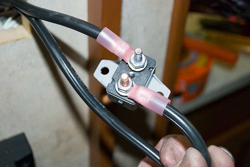
Here's one of the 30 amp circuit breakers 'cut in' to the cable. No reason to pull apart the + and - leads, use a razor knife to separate the wires some, cut the + wire, strip, and crimp on the connectors.
The breakers are mounted. Do not let the breakers flop around, put at least one screw in the mounting tab!
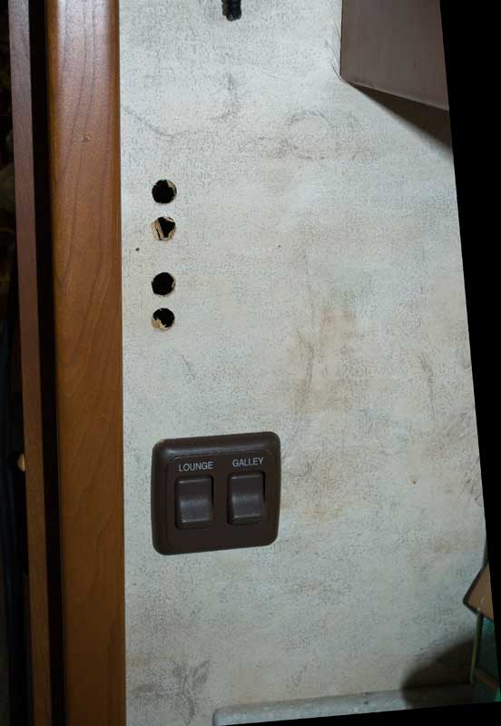
Since we decided to surface mount the charge controller, I had to drill four holes for the wires on the bulkhead,
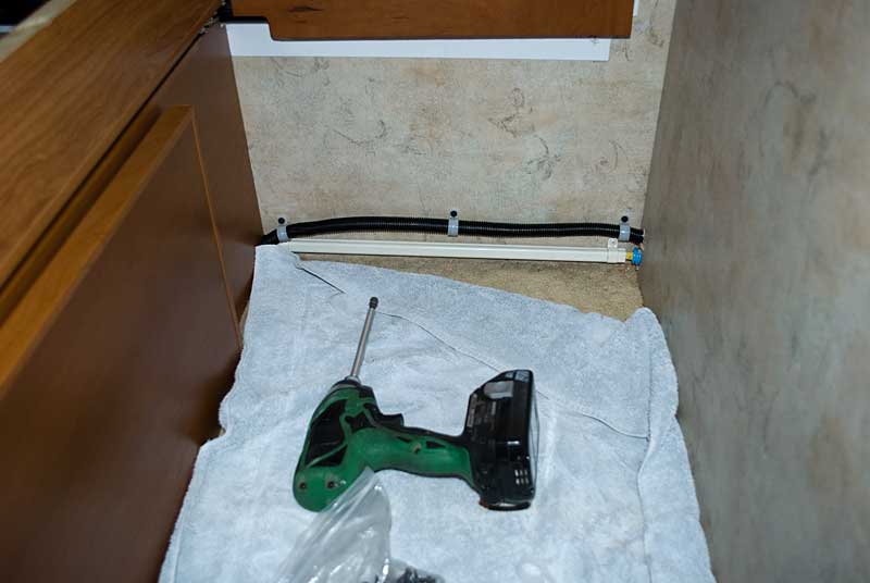
Now we need to run the cable from the controller area to our previously selected DC circuit breaker buss that lives under the bed.
Here I've run the cable down the OnePlace chase/raceway and fished it to this point.
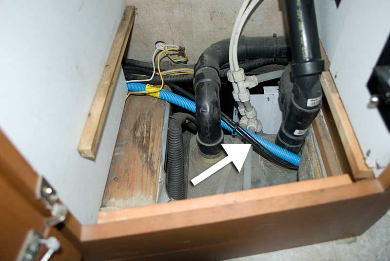
Coming out of the sink area and going back to under the bed. The wiring on the bottom is for the roof air we added a while ago. While this might look ugly, it is actually in a dark corner and very difficult to even see. If I get bothered by it in the future, I'll make a little duct from two strips of 1/8" Luan plywood to cover it up.
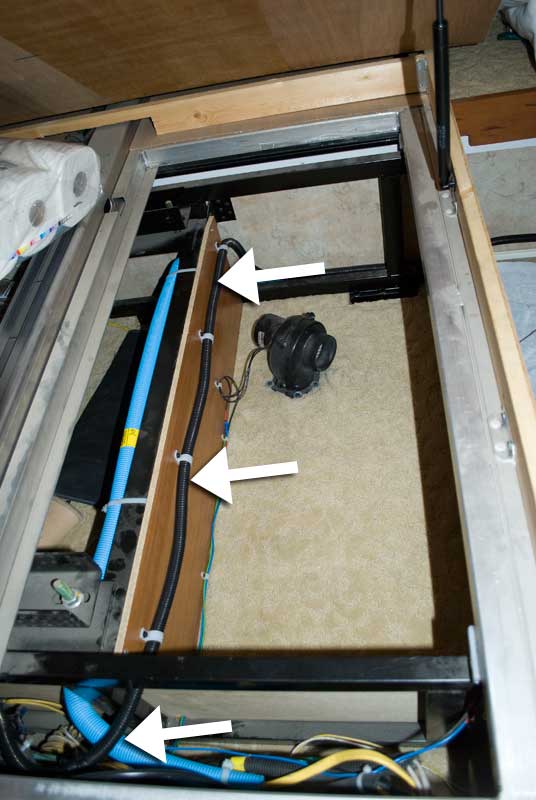
Here's the cable encased in a split wire loom and clamped down under the bed.
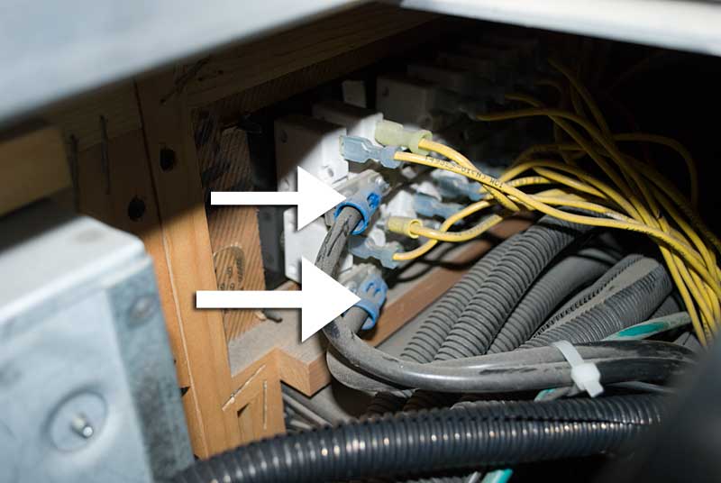
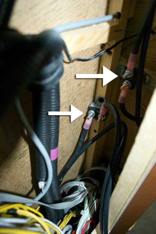
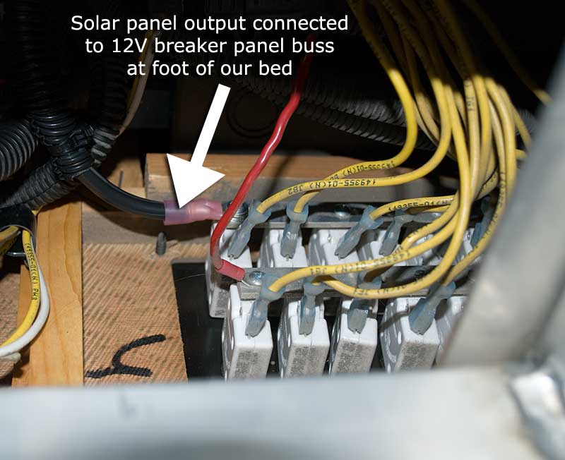
Here's the backside of the DC circuit breaker buss at the foot of our bed. These two marked cables go to the house battery disconnect solenoid. We're going to connect the charge controller output to one of these busses.
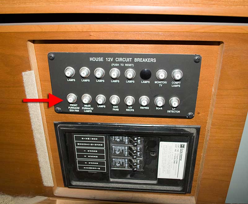
The red arrow points out where we're going to connect the charge controller output (on the backside of course!)
The included (again, if you bought the install kit) solderless terminal ring connector was way too large of diameter for the little screw on the buss, so I resized it - see the next picture.
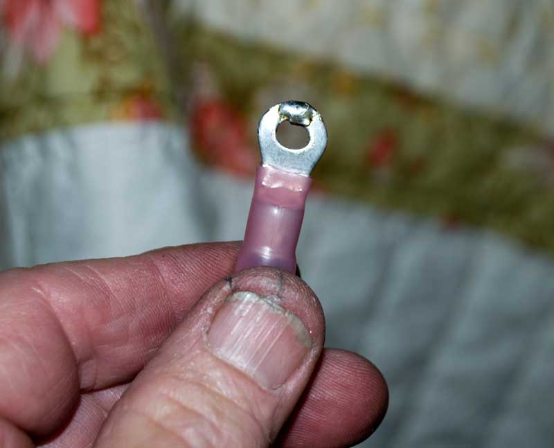
Whoa - ugly thumbnail (and thumb!) Here's the resized connector. Cut a notch out of the ring as required, bend the two ends together and solder (soldering will keep the two legs from coming apart.)
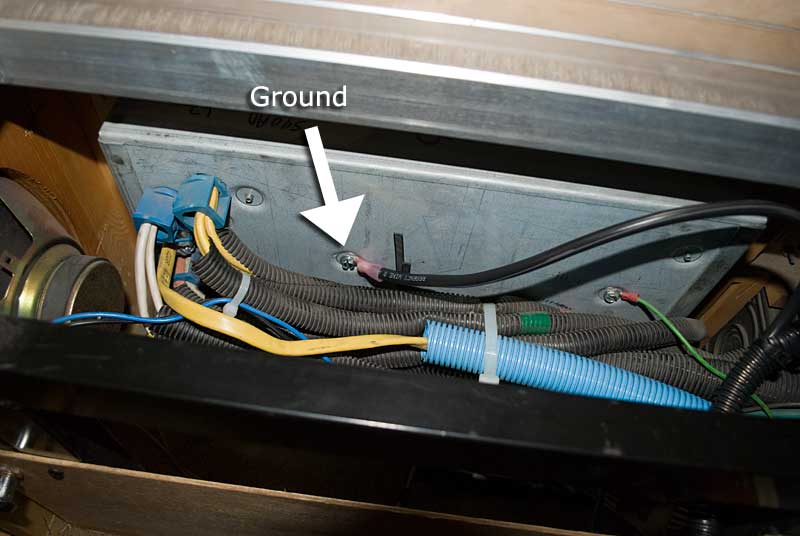
I used the AC circuit breaker box for the ground side of the charge controller output. It's at the same electrical potential as the DC negative side. Note that this is the LAST wire I connected in the entire install - I thought that was the safest way.
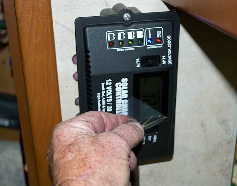
Ah.. getting near the end of the project. Mount the charge controller (if not previously done) and pull off the protective film on the LCD display. If you have AGM or Gel batteries, flip the "Boost Voltage" switch to 14.4V. Traditional flooded cell batteries will be in the 14.7V position.
(I have no idea why they call this "Boost Voltage" - I think it actually is a setting for the limit of the bulk/absorb output voltage stage of three stage charging. AGM/Gel have a different requirement than flooded cell batteries.)
And now - let's take the cardboard off the panels - one last trip to the roof! Let the power begin!!
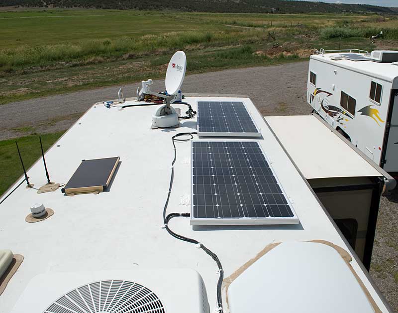
It's alive!! Good job!
Next we'll wrap up the project and discuss performance.
Page 1 - Introduction
Page 2 - Planning
Page 3 - Tools, supplies required, job start
Page 4 - Installation - on the roof
Page 5 -This page
Page 6 - Project wrap-up, final thoughts, panel performance