
 Jane and John's RV pages
We finally kiss the one-thirds goodbye!
Hello Garnet SeeLevel tank monitor system
Winnebago Industries like many other RV manufacturers use a cost-effective tank monitor system which generally only measures the liquid level in the tanks (fresh/gray/black/propane) in one-third or perhaps one-fourth increments which is usually very adequate for the weekender or the owner that travels from full-hookup to full-hookup campgrounds.
(Although the one-third inch resolution is a problem for the propane tank if you don't notice when it just goes below the one-third level - then you could either have almost one-third of a tank of propane available, or be on the verge of empty!)
After grousing about the standard tank monitor practically ever since we owned the Horizon, I finally changed it out for the Garnet SeeLevel system, model 709. Garnet has a bunch of different models - 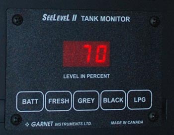 some have a continuous display of tank levels, some have pump and water heater switches, some will monitor two gray tanks, some have a 16" tall sensor strip, etc. I chose the 709 because it was very cost-effective, I did not need any extra switches on its display panel, we only have one gray tank, the #709 only uses a ground a one common wire to all sensor strips, and a 12" tall sensor strip would be adequate.
If you are considering changing your system out for the Garnet SeeLevel, look over the documentation on their web site and/or give them a phone call. I found them to be easy to contact and whoever answered the phone had the answers - there was no chasing down a tech (at least in my experience.)
Important: this write-up is specific to my 2005 Winnebago Industries Horizon 40AD. If you own a 2004-2006 Vectra/Horizon (maybe later model years of the Vectra/Horizon), most if not all of this will apply to your unit. If you don't have one of the upper-tier Winnebago Industries models, you most likely don't have the external tank monitor with the almost ready-to-go wiring. That's not a big deal if you want to add an outside display (highly recommended) - all you need to dig up is a source of +12 volts. Then a small obstacle will be where to mount the outside display, but this should be easily solved.
Caution: please be certain that you have the necessary skills, ability, tools and equipment to safely and competently complete the install. I've made a best effort of providing accurate information, however you assume all of the risk of following my directions and my directions are not guaranteed, nor are your results guaranteed. If you have any doubts about your ability to take on this project, find a good technician to do the job, or you can take the RV to Garnet's Texas location and pay them for the install.
Still with me and ready to give it a go? Let's talk about tools and special tools.
Tools, supplies you will need other than the usual hand tools
Disassembly of the plumbing bay:
Driver drill with a long Phillips bit or extension (8-12") and a shorter bit. One screw near the bay door has a little interference issue with the inside top edge of the bay door
Small right angle Phillips #2 screwdriver to remove one screw (upper right rear of the top panel). The typical 'shortie' Phillips screwdriver is probably too long!
Access to the fresh water tank:
Socket (5/8" I think) and ratchet to back out some bolts along the framework so you can remove part of the Styrofoam to gain access to the right side of the tank wall
Installation of the sensor strips:
220 grit sandpaper on a small flat board to flatten out and roughen up the tank wall
Acetone to remove sanding dust and any crud on the tank wall
Small diameter foam paint roller (sold for trim work) to press the strip against the side of the fresh water tank wall
An 18" tall (approximately) strip of Masonite (or equivalent) used to initially stick the sensor strip to the side of the fresh water tank. It doesn't have to be Masonite - it could be a strip of 1/8" luan. I don't think cardboard has the flex strength to work in this case; you can use something else, but you need the ability to flex the material (with the sensor strip temporarily attached to it with tape) against the side of the tank wall while applying pressure. Whatever you choose, practice with the virgin sensor strip BEFORE you attempt to permanently attach it to the tank!
Electrical connections:
Wire strippers, side cutter, crimp tool (or solder, heat-shrink tubing, small wattage soldering iron), etc., etc.
I chose to solder all connections and use heat-shrink tubing to cover the connection. You could use crimp connectors, but if you do, be certain you have a good connection post-crimp by gently tugging on the wires. One of the issues with crimp connectors is if you are joining dramatically different gauge wires since the connectors are designed for a certain range of wire gauge. If you know how to solder electrical stuff, then I would solder these connections, if not, use crimp connectors but be certain you have a good crimp.
Display installation:
This will depend on your skill level and how well equipped your shop is and what you want the end result to look like. For the inside SeeLevel display, I chose to mount the new display panel in the space of the original monitor. I had to remove the old monitor, its push button switches, and cut the steel to fit the new display. Some have used a surface mount electrical box as a housing to fit the new monitor panel over the existing panel. For the outside display, I used 1/8" birch plywood for a new bezel so I used my woodworking skills and tools. Sorry, but I can't be of more assistance here...
Let's get going!
Please take the time to read through your included SeeLevel Shop Manual before you start. DO NOT use my write-up as your sole source of information since I have not included some installation and testing steps and details!! Please DO use this as a adjunct to the Shop Manual and to help figure out the Winnebago mechanical and electrical particulars.
Since I have so many pictures, you will have to wade through eight pages to look at the entire project write-up. Many of the pictures are available in a very large size (1200 pixels wide), so if you get a little 'hand' when you mouse over a picture, a larger size is available by clicking on the picture.
Page descriptions
>Page 1 - this page - project introduction
Page 2 - pictures of the 'special tools' and jigs I used, picture of the Garnet system, disassembly of the plumbing bay part 1
Page 3 - we finish disassembly of the plumbing bay and look at wiring
Page 4 - we test and finish up sensor strip installation
Page 5 - building a bezel for the outside display, finishing up the outside
Page 6 - access to the fresh water tank, installing the sensor strips on the tank wall, sensor wiring
Page 7 - we start installing the inside display, removal of the old display board & switches, cutting off the solar panel part of the old circuit board (optional), cutting an opening in the OnePlace steel panel for the new display
Page 8 - Wiring and project wrap-up